Note: This article is prepared for web publishing in clean HTML and contains no embedded source links or placeholder citation tags.
When a Measuring Tool Becomes a Mechanical Showpiece
Most makers use calipers to check 3D prints. That is normal, sensible, and unlikely to make anyone spill coffee on their keyboard. But a 3D printed caliper flips the script: instead of using a measuring tool to improve a print, the print becomes the measuring tool. Even better, the most eye-catching version works like a tiny clockwork machine, complete with racks, pinions, spinning dials, and the sort of mechanical drama usually reserved for pocket watches and steampunk movie props.
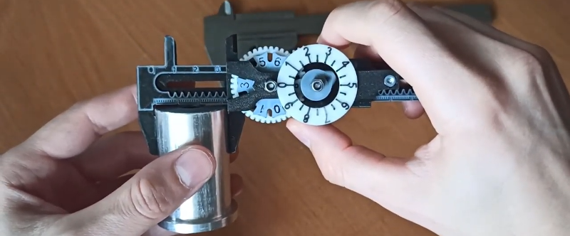
The idea behind 3D printed calipers is simple enough: create a sliding measuring tool that can read outside dimensions, inside dimensions, and sometimes depth, just like a conventional caliper. The magic is in how the reading appears. Instead of a plain digital screen, the clockwork-style design uses a linear rack and small gears to translate jaw movement into rotating indicators. A window may show tens of millimeters, while separate dials show smaller units and decimal values. It is part measuring device, part mechanical puzzle, and part “please watch this gear spin again.”
Are these calipers ready to replace a certified Mitutoyo, Starrett, or Brown & Sharpe tool in a machine shop? No. Let us not invite chaos into the inspection room. But as a 3D printing project, educational tool, and mechanical design exercise, they are brilliant. They demonstrate gear ratios, dimensional accuracy, backlash, tolerance, material behavior, assembly design, and the limitations of plastic parts in one compact object. In other words, they are a tiny engineering classroom with jaws.
What Makes a Clockwork 3D Printed Caliper Different?
A standard digital caliper uses electronics and a linear scale to display measurements. A dial caliper uses a rack and pinion to move a needle across a circular dial. A vernier caliper uses carefully aligned scales and a patient human eye. A 3D printed clockwork caliper borrows from these ideas but adds a playful mechanical display. Instead of hiding the motion, it celebrates it.
In the well-known DIY design that inspired the “work like clockwork” phrase, the printed caliper uses multiple STL parts, including a linear sprocket or rack, sleeve components, wheels, pointers, a dial, a depth gauge, washers, and small hardware such as M3 screws and nuts. The original design was printed in PLA on a common desktop printer with a 0.4 mm nozzle, 0.2 mm layer height, and modest infill. That matters because it proves the concept is not limited to exotic industrial machines. A hobby printer in decent condition can produce a functioning mechanical measuring tool, provided the user is willing to tune, test, and occasionally whisper motivational words at the printer.
The design’s published specifications claimed a metric unit system, approximate accuracy around plus or minus 0.1 mm, resolution around 0.05 mm, and a standard measuring length around 110 mm, with mini and long versions also added later. Those numbers are respectable for a printed project, but they should be understood in context. A 3D printed caliper can be useful for demonstrations, rough measurements, repeatable comparisons, and maker education. It should not be treated as a calibrated inspection instrument for safety-critical or high-precision parts.
How the Mechanism Works
The Sliding Jaw
At the heart of any caliper is sliding motion. One jaw remains fixed while the other moves along a beam. When you close the jaws around a part, the distance between them becomes the measurement. In a simple printed caliper, the user might read the value from a printed scale. In the clockwork version, that sliding movement drives a mechanical display.
The Rack and Pinion
The rack is a straight toothed bar. The pinion is a small gear that meshes with it. When the jaw slides, the rack moves, and the pinion rotates. This is the same basic idea used in dial calipers, steering systems, and many linear-to-rotary mechanisms. The beauty of rack-and-pinion motion is that it converts a straight measurement into rotation, which can then be amplified, reduced, or divided across a gear train.
The Gear Train
Once rotation begins, gears can turn pointers, number wheels, or dials. This is where the caliper earns its clockwork personality. A gear train can divide motion into readable steps, allowing one dial to show whole millimeters and another to show fractions. It looks fancy because it is fancy. It is also a reminder that old mechanical solutions still have a lot to teach modern makers. Sometimes the best interface is not a screen; it is a wheel that turns with satisfying confidence.
The Depth Gauge
Many calipers include a depth rod that extends from the end of the beam as the jaws open. The 3D printed version may include a printed depth gauge as well. This feature is useful for measuring hole depth, slot depth, or recesses. In a printed tool, it is less about laboratory-grade accuracy and more about understanding the geometry of caliper functions.
Why 3D Printing This Tool Is So Interesting
3D printing is especially good at making complex shapes quickly. Additive manufacturing builds parts layer by layer from a digital model, allowing designers to create forms that would be inconvenient, expensive, or just plain annoying to make with traditional subtractive methods. That is why a 3D printed caliper is more than a novelty. It is a compact demonstration of what digital fabrication does well: rapid iteration, custom geometry, integrated mechanical features, and low-volume experimentation.
If the first gear is too tight, the designer can add clearance and print again. If the pointer flexes, the part can be thickened. If the sleeve drags, a “looser” version can be uploaded. If the long version needs more stiffness, ribs or thicker sections can be added. This is the maker workflow in miniature: design, print, test, grumble politely, redesign, print again.
That iterative loop is exactly why functional 3D printed tools are so valuable. A printed caliper teaches that every CAD dimension has to survive the real world. Filament expands and contracts. Corners bulge. Holes print undersized. Thin parts flex. Layer lines influence strength. Supports can roughen surfaces. Suddenly, “make it 10 mm wide” becomes a fascinating negotiation between software, plastic, heat, motion, and gravity.
Accuracy, Precision, and the Big Reality Check
To understand 3D printed calipers, it helps to separate three often-confused terms: accuracy, precision, and resolution. Accuracy means how close the reading is to the true value. Precision means how repeatable the reading is. Resolution means the smallest increment the tool can display. A tool can show 0.05 mm increments and still be inaccurate if the mechanism has backlash or the plastic body flexes.
This distinction is not academic hair-splitting. It is the difference between a tool that looks precise and a tool that measures reliably. A printed caliper may repeat the same reading when measuring the same object, which makes it useful for comparison. But if it consistently reads 20.10 mm when the true value is 20.00 mm, it is precise but not accurate. That is still useful in some maker workflows, but it is not the same as certified metrology.
Commercial calipers are usually made from metal, ground surfaces, controlled mechanisms, and standards-based calibration processes. They resist flex better than plastic. They are less affected by temperature and humidity. They have carefully manufactured measuring faces. A PLA caliper, by contrast, is lighter, softer, and more sensitive to heat. Leave it in a hot car and it may return with opinions.
The Role of Tolerances in a Printed Caliper
A clockwork caliper depends on many moving parts, and every moving part needs clearance. If the gears are modeled with perfect theoretical contact, they may fuse, grind, or jam after printing. If the clearances are too large, the mechanism develops backlash, which means the display may lag or shift when changing direction. This is the eternal 3D printing comedy: too tight and nothing moves; too loose and everything moves except the measurement you wanted.
For functional 3D printed assemblies, designers often test clearances using small calibration models before committing to a complex build. FDM printers may need larger gaps than resin printers because the extruded filament bead, layer height, cooling behavior, and machine calibration all influence final dimensions. SLA resin printers can produce finer details and smoother surfaces, but resin shrinkage, curing, and support removal still matter.
In a caliper, tolerance problems multiply. A small error in the rack tooth spacing affects gear rotation. A small error in gear diameter affects pointer position. A small amount of jaw flex affects the measurement. Add them together, and a beautiful mechanism can become a very decorative liar. That does not make the project bad. It makes it educational. The caliper becomes a hands-on lesson in tolerance stack-up.
Materials: PLA, PETG, Resin, and the Search for Smooth Motion
PLA is popular for this type of project because it is easy to print, stiff enough for small mechanisms, and dimensionally friendly compared with some other common filaments. It is also widely available and inexpensive. For a display project or classroom demonstration, PLA is a sensible choice.
PETG offers improved toughness and temperature resistance, but it can be stringier and slightly more flexible, which may affect crisp gear teeth and sliding surfaces. ABS and ASA can handle heat better but introduce warping concerns. Nylon is strong and slippery, but it absorbs moisture and can be harder to print well. Resin printing can produce finer detail, which is attractive for small gears and dial components, though cured resin may be brittle depending on the formulation.
The best material depends on the goal. If the goal is a visually impressive desk object that actually moves, PLA is usually enough. If the goal is smoother miniature gears, resin may be appealing. If the goal is durability, consider tougher engineering materials, but expect more tuning. No material magically removes the need for calibration and careful design. Unfortunately, there is no filament called “Instant Accuracy Pro.” The world remains unfair.
Practical Uses for 3D Printed Calipers
A 3D printed caliper is not the tool you choose for aerospace inspection or machining a bearing seat. However, it can be useful in several realistic contexts.
Education
Teachers and workshop instructors can use a printed caliper to explain mechanical measurement, gear ratios, sliding mechanisms, backlash, and additive manufacturing limits. Students can see how linear motion becomes rotary motion and how small design choices influence performance.
Design Demonstration
For makers, the caliper is a portfolio piece. It says, “I understand assemblies, tolerances, gears, and print settings.” That is more impressive than another cube, unless the cube also makes coffee.
Rough Workshop Measurement
A well-tuned printed caliper may help with quick, non-critical measurements, especially when repeatability matters more than absolute accuracy. It can be useful for checking approximate dimensions of printed parts, comparing prototypes, or teaching beginners how calipers work before handing them a more expensive tool.
Customization
Because the design is digital, it can be resized, modified, color-coded, labeled, or adapted for special demonstrations. Want giant classroom calipers? Possible. Want transparent resin gears? Tempting. Want a caliper shaped like a dragon? Please consult your local maker with too much filament and not enough supervision.
Challenges Designers Must Solve
The first challenge is smooth motion. The slider must move freely without wobbling. The jaws must align. The rack must engage consistently with the pinion. The gear train must rotate without binding. Each of these problems sounds small until they all arrive at once like uninvited relatives.
The second challenge is backlash. Gears need clearance to move, but clearance creates play. When the jaw changes direction, the gear teeth may shift before the pointer responds. This can cause different readings depending on whether the caliper approaches a measurement from open-to-closed or closed-to-open. Higher-end mechanical designs reduce backlash with spring loading, split gears, or more controlled manufacturing, but those solutions are harder to print cleanly.
The third challenge is stiffness. Measuring jaws must not flex too much under normal hand pressure. Plastic jaws can bend, especially near the tips. Users can reduce error by applying light, consistent pressure and measuring closer to the stronger base of the jaws when possible.
The fourth challenge is calibration. Even if the caliper moves beautifully, it should be checked against known objects. Gauge blocks are ideal, but common reference items can help for casual testing. Measure the same object several times. Check zero. Open and close the jaws. Compare readings against a trusted caliper. If the tool repeats well but reads slightly off, the scale or gear ratio may need adjustment.
How to Improve a 3D Printed Caliper
Start with printer calibration. Check extrusion multiplier, belt tension, steps per millimeter, first-layer squish, and dimensional accuracy using a test print. A caliper project exposes printer errors quickly because it relies on sliding and meshing parts.
Next, print small test sections before printing the full tool. A short rack and gear pair can reveal whether the teeth mesh correctly. A sleeve and slider sample can show whether the moving jaw will glide or behave like it has taken a vow of stillness.
Use sensible orientation. Parts with teeth may print better when the tooth profile is clean and supported properly. Sliding surfaces should be placed to minimize rough support scars. For FDM printing, layer direction affects strength and surface finish. For resin printing, orientation affects support marks, cure behavior, and warping.
Post-processing matters. Light sanding, deburring, and cleaning can dramatically improve motion. A tiny burr on a gear tooth may cause a dramatic jam, because small mechanisms are divas. Dry lubricant may help in some assemblies, but use it carefully and avoid anything that attacks the plastic.
Why This Project Captures the Spirit of Making
The charm of 3D printed calipers is not that they beat commercial tools. They do not need to. Their value is that they make measurement visible. They reveal the hidden dance inside mechanical tools: the sliding beam, the rack, the pinion, the pointer, the scale, the zero point, and the relationship between motion and information.
Digital tools are wonderfully convenient, but they often hide their logic behind screens and chips. A clockwork caliper puts the logic on display. When the jaw moves, the gears turn. When the gears turn, the dial changes. The user can see cause and effect. That makes the tool memorable, especially for beginners who are learning why measurement is more than reading numbers.
It also shows the playful side of engineering. Not every useful project must be strictly practical. Some projects are worth building because they make people lean closer and say, “Wait, how does that work?” That moment is powerful. Curiosity is the gateway drug of engineering, and this caliper is basically a tiny mechanical dealer wearing PLA shoes.
Experience Notes: What Building and Using One Teaches You
Working with a 3D printed clockwork caliper feels different from printing a decorative model. A vase can look good even if it is slightly off. A caliper immediately complains. If the rack is rough, the pointer stutters. If the sleeve is tight, the jaw drags. If the gears are loose, the reading changes depending on direction. The project politely forces you to become a better printer operator.
One of the first lessons is that “printer works fine” is not the same as “printer is ready for mechanisms.” A machine can produce attractive figurines and still struggle with interlocking parts. Functional prints demand cleaner extrusion, better cooling, consistent wall dimensions, and reliable first layers. Elephant’s foot at the bottom of a part may be harmless on a toy, but on a sliding mechanism it becomes a tiny plastic speed bump with big ambitions.
The second lesson is patience. A printed caliper may need several rounds of tuning. The first version might assemble but feel stiff. The second might move smoothly but read poorly. The third might be close, except one gear tooth clicks at the same position every time. This is not failure; it is mechanical editing. Writers revise sentences. Makers revise clearances.
The third lesson is measurement discipline. When using a printed caliper, consistent pressure matters. Squeezing too hard can flex the jaws and change the reading. Measuring with the jaw tips may give different results than measuring nearer the base. Closing the jaws to check zero becomes a habit. Comparing against a trusted caliper teaches the difference between a fun tool and a reliable reference instrument.
The fourth lesson is design respect. Commercial calipers look simple because skilled engineers made them simple for the user. Behind that simplicity are material choices, standards, calibration methods, surface finishes, and decades of refinement. Printing a caliper at home makes you appreciate why good measuring tools cost money. It also makes you appreciate how much can be achieved with a desktop printer, a clever model, and a handful of screws.
Perhaps the best experience is showing the finished caliper to someone else. Slide the jaw, let the wheels turn, and watch the reaction. People understand rulers. They understand gears. But combining them in a printed object creates a delightful surprise. Even if the tool never becomes your daily measurement device, it becomes a conversation starter, a teaching aid, and a reminder that 3D printing is not only about making parts. It is about making ideas move.
Conclusion
3D printed calipers work like clockwork because they transform measurement into visible mechanical motion. They combine practical tool design with the theatrical charm of gears and dials. While they should not replace certified calipers for precision inspection, they are an outstanding project for learning about additive manufacturing, mechanical tolerances, gear trains, backlash, calibration, and the real-world behavior of printed plastic.
The project’s real success is not just that it measures. It teaches. It shows how a printer’s accuracy affects moving parts, how clearances make or break assemblies, and how old-school mechanical design still has plenty of sparkle in the digital fabrication age. For makers, educators, and curious engineers, a 3D printed clockwork caliper is more than a novelty. It is a small machine that turns plastic, patience, and clever design into motion you can see.