Note: This article is synthesized from real electronics documentation, manufacturer wiring guides, stepper-driver references, and practical troubleshooting advice from reputable U.S.-focused technical sources including electronics educators, component distributors, and motion-control manufacturers.
Introduction: When a Stepper Motor Looks Like a Tiny Bowl of Spaghetti
Deducing stepper motor wiring is one of those workshop tasks that seems mysterious until you do it once. Then it becomes almost suspiciously simple, like finding out the “secret code” was just a multimeter, patience, and not trusting wire colors with your entire soul. Stepper motors are everywhere: 3D printers, CNC machines, camera sliders, robotics projects, lab equipment, plotters, and that one ambitious DIY machine in the garage that currently makes more noise than progress.
The problem usually begins when you have a motor with four, five, six, or eight wires and no trustworthy datasheet. Maybe the label is scratched off. Maybe the motor came from a surplus bin. Maybe the manufacturer used wire colors that appear to have been chosen during a lunch break. Whatever the case, the goal is the same: identify the motor coils, determine which wires belong together, and connect them correctly to a stepper driver.
This guide explains how to deduce stepper motor wiring using practical methods, especially resistance testing with a digital multimeter. We will cover bipolar stepper motors, unipolar stepper motors, center taps, coil pairs, series and parallel wiring, and common mistakes that make motors buzz, shake, overheat, or spin like they have just remembered an unpaid bill.
What Makes Stepper Motor Wiring Different?
A stepper motor does not spin freely like a basic DC motor. Instead, it moves in controlled increments called steps. Inside the motor are electromagnetic windings, usually organized into phases. A stepper driver energizes these phases in a sequence, pulling the rotor from one magnetic position to the next. That is why stepper motors are popular when a project needs precise positioning without necessarily using a feedback encoder.
Wiring matters because the driver must energize the correct coils in the correct relationship. If the coil wires are mixed up, the motor may vibrate, lock in place, jump randomly, rotate weakly, or refuse to move at all. It is not being dramatic; it simply cannot follow the electrical choreography.
Most hobby and industrial stepper systems use either bipolar or unipolar wiring. A bipolar stepper motor typically has two independent windings and needs current to flow both directions through each coil. A unipolar stepper motor has center-tapped windings, allowing current to flow through half of a winding at a time. Modern chopper drivers, such as common step-and-direction drivers, are usually designed for bipolar motors, but many six-wire and eight-wire motors can be connected for bipolar operation if you identify the correct wires.
First Clue: Count the Wires
The fastest first step in deducing stepper motor wiring is counting the leads. The number of wires does not tell you everything, but it gives you a strong starting point.
Four-Wire Stepper Motor
A four-wire stepper motor is usually bipolar. It has two separate coils, and each coil has two ends. Your job is to find which two wires form coil A and which two form coil B. This is the simplest case and the most common in 3D printers, small CNC machines, and Arduino-style motion projects.
Five-Wire Stepper Motor
A five-wire stepper motor is usually unipolar with the center taps internally joined. This style can be awkward with many modern bipolar drivers because the shared common wire connects the centers of both phases. In many cases, a five-wire motor should be driven as a unipolar motor, not as a true bipolar motor, unless you are willing to modify the motor internally, which is rarely worth the tiny adventure and possible smoke show.
Six-Wire Stepper Motor
A six-wire stepper motor usually has two windings, and each winding has a center tap. That gives you three wires per phase: one end, the center tap, and the other end. You can often use this motor with a bipolar driver by ignoring the center taps and connecting only the two outer ends of each winding.
Eight-Wire Stepper Motor
An eight-wire stepper motor offers the most flexibility. It usually has four separate half-windings. These can often be connected in series or parallel to create two complete phases. Series wiring can be useful for lower-speed torque, while parallel wiring can support better high-speed performance if the driver can supply the required current. Eight-wire motors are versatile, but they demand careful identification.
Tools You Need to Identify Stepper Motor Wires
You do not need a laboratory full of equipment to deduce stepper motor wiring. You need a few basic tools and the ability to resist the temptation to “just try it.” Electronics rewards curiosity, but it charges extra for impatience.
- A digital multimeter with resistance or continuity mode
- Masking tape or small labels for marking wires
- A notebook or spreadsheet for recording resistance readings
- The motor’s datasheet, if available
- A suitable stepper driver with current limiting
- A power supply matched to the driver and motor system
The multimeter is the star of the show. A stepper motor coil is simply a length of copper wire wound inside the motor. If two external wires are connected to the same coil, your multimeter will show a low resistance between them. If two wires are not connected to the same coil, the meter will show open circuit or very high resistance.
Safety Before Testing: Save the Driver, Save the Day
Before connecting or disconnecting motor wires, power down the driver. Many stepper driver boards can be damaged if the motor is unplugged while the driver is energized. A stepper coil is an inductor, and inductors can create voltage spikes when current is interrupted. That little spark of chaos can be enough to ruin a driver module.
Also remember that stepper motors can get warm during normal operation. They often draw holding current even when they are not moving. Warm is common; “too hot to touch” deserves investigation. Incorrect wiring, excessive current limit, poor cooling, or the wrong motor-driver pairing can all turn a neat motion project into a tiny desk heater.
The Basic Multimeter Method for Four-Wire Motors
For a four-wire bipolar stepper motor, the process is beautifully straightforward.
- Set the multimeter to resistance mode.
- Pick one wire and test it against each of the other three wires.
- When the meter shows a low resistance, those two wires are one coil pair.
- The remaining two wires should form the second coil pair.
- Label the pairs as A and B.
For example, suppose the motor has red, green, blue, and yellow wires. You measure between red and green and see 2.8 ohms. Then you measure between blue and yellow and see 2.8 ohms. The other combinations show open circuit. That means red-green is one coil, and blue-yellow is the other coil.
Does it matter which coil is called A and which is called B? Usually, not much. If the motor spins the wrong direction, you can reverse one coil pair or change the direction setting in software. What matters is that each driver output phase connects to one complete motor coil. Do not connect one wire from coil A and one wire from coil B to the same driver phase unless you enjoy watching machinery perform interpretive dance.
How to Connect Coil Pairs to a Driver
Most bipolar stepper drivers have output labels such as A+, A-, B+, and B-, or sometimes 1A, 1B, 2A, and 2B. One coil goes to the A terminals, and the other coil goes to the B terminals.
Using the previous example:
- Red and green go to A+ and A-
- Blue and yellow go to B+ and B-
If the motor rotates backward, reverse one pair, such as swapping red and green. You can also reverse the direction pin logic in the controller. Both methods change direction; neither changes the identity of the coil pair.
Deducing Six-Wire Stepper Motor Wiring
Six-wire motors require one extra layer of detective work because each phase has a center tap. In resistance testing, this means each group of three related wires will show continuity with one another. The center tap will show about half the resistance to either end compared with the resistance measured between the two outer ends.
Imagine a six-wire motor with these measured values:
- Red to white: 1.5 ohms
- White to blue: 1.5 ohms
- Red to blue: 3.0 ohms
In this group, white is likely the center tap, while red and blue are the outer ends of the winding. If you are using a bipolar driver, you would usually leave white disconnected and connect red and blue as one phase. Repeat the same process for the other three-wire group.
If you are using a unipolar driver, the center taps matter. The center tap often connects to the supply side, while the driver switches current through each half-winding. Always match the wiring approach to the driver type. A bipolar driver and a unipolar driver do not ask the motor to do the same electrical job.
Deducing Five-Wire Stepper Motor Wiring
Five-wire stepper motors are common in older equipment and small geared steppers. They usually have a shared common wire connected to the center taps of both windings internally. When testing with a multimeter, the common wire often shows similar lower resistance to several other wires, while resistance between the outer wires may be higher or may trace through the shared center connection.
The challenge is that the shared common prevents the two phases from being fully isolated. Many bipolar stepper drivers expect two independent coils. A five-wire motor does not give them that clean separation. For that reason, five-wire motors are best used with proper unipolar driver circuits unless the motor is specifically documented as compatible with your driver.
The practical rule is simple: if you have a five-wire motor and a common bipolar driver module, pause before connecting. Look up the motor model, verify the wiring, and understand the driver requirements. Guessing here can lead to poor performance, overheating, or driver damage.
Deducing Eight-Wire Stepper Motor Wiring
An eight-wire motor can feel intimidating, but the logic is still based on resistance. You are looking for four separate coil sections. Each pair of wires that shows low resistance belongs to one half-winding. Once you identify the four pairs, you must determine which two half-windings belong to phase A and which two belong to phase B, then decide whether to wire them in series or parallel.
In series wiring, two related half-windings are connected end-to-end. This increases resistance and inductance, which can be useful at lower speeds but may limit high-speed performance. In parallel wiring, matching half-windings are connected side by side. This lowers effective resistance and inductance, allowing faster current rise, but it requires a driver that can supply more current.
The best source for an eight-wire motor is always the datasheet. If the datasheet is unavailable, you can still identify the individual pairs with a multimeter, but determining phase relationship and polarity may require careful testing at low current. A current-limited bench supply or proper stepper driver setup is helpful. This is where method beats bravery.
The “Short Two Wires and Feel the Shaft” Trick
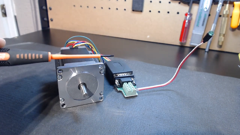
There is a classic hands-on trick for identifying stepper coil pairs. With the motor disconnected from power, short two wires together and gently rotate the shaft by hand. If the two wires are part of the same coil, the motor shaft will usually feel harder to turn because the spinning rotor induces current in the shorted winding, creating magnetic resistance. If the wires are unrelated, the shaft will feel mostly unchanged.
This method is useful when you do not have a multimeter nearby, but the multimeter method is more reliable and more precise. The shaft-feel test is like checking tire pressure with your shoe. It can give you a clue, but please do not make it your entire engineering department.
Why Wire Colors Cannot Always Be Trusted
Many online examples say that red and blue are one coil, or green and black are another. Sometimes that is true. Sometimes it is absolutely not. Stepper motor wire colors vary by manufacturer, model, production batch, and cable assembly. Even motors with the same frame size, such as NEMA 17, can have different color codes.
This is why deducing stepper motor wiring should be based on continuity and resistance, not color alone. Wire color is a hint, not evidence. The multimeter is evidence.
Common Symptoms of Incorrect Stepper Motor Wiring
If a stepper motor is wired incorrectly, it usually complains immediately. It may not use words, but it has a dramatic vocabulary.
The Motor Vibrates but Does Not Rotate
This often means the coil pairs are mixed. The driver is energizing wires that do not belong to the same phase, so the magnetic fields are fighting instead of rotating in sequence.
The Motor Moves Erratically
Erratic movement can come from swapped wires, loose connections, poor grounding, inadequate power supply current, or acceleration settings that are too aggressive. Start by confirming coil pairs.
The Motor Runs Backward
This is not usually a wiring failure. Reverse one coil pair or change the direction setting in software.
The Motor Gets Very Hot
Stepper motors often run warm, but excessive heat can mean the current limit is set too high, the driver is poorly cooled, or the motor is wired in a way that changes the expected current requirement.
The Driver Gets Hot or Fails
Driver overheating may be caused by excessive current, lack of heat sinking, poor airflow, shorted outputs, or disconnecting the motor while powered. Small driver boards can be powerful, but they are not magic. They need sane settings and cooling.
Current Limit Matters More Than Guessing Voltage
Many beginners see a motor labeled “2.8 V” or “3.2 V” and panic when a driver uses a 12 V or 24 V supply. In modern stepper systems, the driver usually limits coil current electronically. The supply voltage helps current rise quickly through the motor windings, while the current limit protects the motor and driver.
This is why setting the driver current limit is critical. The motor’s rated current tells you the safe phase current under specified conditions. If you exceed it, the motor may overheat. If you set it too low, the motor may skip steps or lose torque. The correct setting depends on the motor rating, driver design, cooling, wiring mode, and application.
Practical Example: Identifying a Mystery Four-Wire Stepper
Let’s say you salvaged a four-wire stepper motor from an old scanner. The wires are black, green, red, and blue. No label. No datasheet. No manufacturer name. Just a small motor silently judging you.
You measure resistance:
- Black to green: open circuit
- Black to red: 4.1 ohms
- Black to blue: open circuit
- Green to blue: 4.0 ohms
- Green to red: open circuit
- Red to blue: open circuit
The answer is clear: black-red is one coil, and green-blue is the other. You label black-red as phase A and green-blue as phase B. Then you connect black and red to A+ and A-, green and blue to B+ and B-. If the direction is wrong, swap black and red, or change the direction logic in your controller.
Practical Example: Identifying a Six-Wire Stepper
Now suppose you have a six-wire motor with orange, yellow, brown, black, white, and red wires. You test and find these groups:
- Orange to yellow: 2 ohms
- Yellow to brown: 2 ohms
- Orange to brown: 4 ohms
- Black to white: 2 ohms
- White to red: 2 ohms
- Black to red: 4 ohms
Yellow and white are likely center taps. For bipolar operation, you would leave yellow and white disconnected, then use orange-brown as one phase and black-red as the other. For unipolar operation, the center taps would be part of the driver wiring. This example shows why resistance values are so useful: the center tap reveals itself by being halfway between the two ends.
How to Label Stepper Motor Wires Like a Professional
Once you identify the wires, label them. Do not tell yourself, “I’ll remember.” You will not. Future you will look at the motor six weeks later and wonder why past you was so confident and so unhelpful.
Use tape flags, heat-shrink labels, or small printed tags. Label the wires as A+, A-, B+, and B- only after you decide how they connect to the driver. For six-wire motors, mark center taps clearly as CT-A and CT-B. For eight-wire motors, document each half-winding pair and the final series or parallel configuration.
A simple wiring note might look like this:
That tiny note can save an hour later. It can also prevent the ancient workshop ritual known as “re-solving a problem you already solved.”
Best Practices for Connecting to a Stepper Driver
Once you identify the wiring, connect the motor carefully. Confirm that the driver is designed for the motor type. Use a current-limited driver for most bipolar stepper motors. Set the current limit before demanding full torque. Provide cooling if the driver requires it. Keep motor wires secure, because intermittent connections can cause missed steps or voltage spikes.
Do not connect or disconnect the motor while the system is powered. Do not assume the power supply current equals coil current. Do not run the driver without understanding its current-setting method. And do not rely on wire colors unless the motor datasheet confirms them. The datasheet is the map; the multimeter is the compass.
Troubleshooting Checklist
If the motor does not behave correctly, work through the problem in a logical order:
- Power off the system.
- Recheck coil pairs with the multimeter.
- Confirm each coil goes to one driver phase.
- Check for loose terminals or broken wires.
- Verify driver current limit.
- Confirm motor supply voltage is within the driver’s allowed range.
- Reduce speed and acceleration in software.
- Test direction by swapping one coil pair or changing software direction.
- Check driver temperature and cooling.
- Consult the motor datasheet if available.
Most stepper wiring problems are not mysterious once you slow down and measure. The motor is not trying to ruin your day. It is simply waiting for you to introduce the correct wires to the correct terminals.
Experience Section: Lessons from Deducing Stepper Motor Wiring in Real Projects
After working with stepper motors in hobby machines, repair projects, 3D printer upgrades, and oddball salvage builds, one lesson becomes obvious: the wiring problem is rarely difficult, but it is very easy to make difficult. The most common mistake is starting with assumptions. Someone sees red, blue, green, and black wires and immediately copies a diagram from a different motor. Sometimes the motor runs. Sometimes it vibrates like an angry electric toothbrush. Sometimes the driver gives up and becomes a tiny, expensive paperweight.
The best experience-based habit is to treat every unknown motor as unknown, even when it looks familiar. I have seen two motors with the same frame size and nearly identical cable colors use different coil pairings. I have also seen used motors with replacement cables where the colors meant absolutely nothing. In one case, the cable had been extended with whatever wire was available, producing a cheerful rainbow of lies. The multimeter solved the puzzle in under two minutes.
Another useful lesson is to write everything down before connecting the driver. During a project, it feels faster to keep the wiring in your head. But when you are also configuring firmware, setting microsteps, checking belt tension, and wondering why the Y-axis thinks it is a percussion instrument, memory becomes unreliable. A small label on each wire and a note in the project folder can prevent repeated testing.
Six-wire motors are especially good teachers. At first, the center tap seems confusing. Then you measure the resistance and notice the pattern: half resistance from center to either end, full resistance from end to end. Once that clicks, six-wire motors stop looking strange. You simply decide whether the driver needs the center taps or whether they should be insulated and left unused.
Eight-wire motors teach a different lesson: flexibility comes with responsibility. Series and parallel wiring can both be correct, depending on the driver and performance goal. A motor wired in series may behave nicely at lower speeds but lose torque earlier as speed rises. A motor wired in parallel may perform better at speed but requires more current. The wiring decision should match the machine, not just the first diagram found online.
One practical trick is to test motion gently at first. Use a conservative current setting, low speed, and low acceleration. A correctly wired stepper should rotate smoothly under simple commands. If it buzzes, jumps back and forth, or locks strangely, stop and recheck wiring before increasing power. More current will not fix crossed coils; it will only make the wrong thing happen with greater confidence.
Finally, deducing stepper motor wiring builds a useful mindset for electronics work in general. Measure first. Label clearly. Change one variable at a time. Do not trust color codes blindly. Respect driver limits. And never underestimate how satisfying it feels when a mystery motor finally turns smoothly, as if it had been waiting the whole time for someone to ask the right questions.
Conclusion: The Mystery Is in the Method, Not the Motor
Deducing stepper motor wiring is a practical skill that turns confusion into control. Whether you are working with a four-wire bipolar motor, a six-wire unipolar motor, a five-wire salvage part, or an eight-wire industrial stepper, the basic process begins with identifying coils. A digital multimeter, careful resistance measurements, and good labeling habits will solve most wiring puzzles before power is ever applied.
The most important rule is simple: connect each driver phase to one complete motor coil. Once the coil pairs are known, direction and performance can be adjusted through wiring orientation, driver settings, current limits, and software configuration. Stepper motors may look cryptic at first, but they are wonderfully logical once you understand what the wires represent.
So the next time a stepper motor arrives with no datasheet, no markings, and a cable that looks like it escaped from a confetti cannon, do not panic. Grab the multimeter, find the coil pairs, label the leads, and proceed like the calm, capable motion-control detective you are.