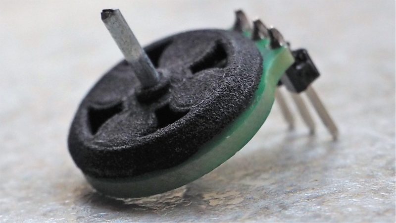
Some inventions arrive with dramatic music, smoke machines, and a marketing budget large enough to power a small moon. Others quietly spin on a workbench and make engineers lean forward like cats watching a laser pointer. A tiny motor built into a PCB belongs firmly in the second group. It looks almost too simple: a printed circuit board, copper traces arranged like elegant little spirals, a rotor with magnets, a bearing, and enough clever design work to make a normal motor feel overdressed.
At its core, a PCB motor turns the circuit board itself into part of the machine. Instead of using traditional wound copper coils wrapped around an iron core, the motor’s stator can be created directly from copper patterns etched into the printed circuit board. That means the same board that carries electronics can also generate motion. In tiny robotics, haptic feedback, kinetic art, experimental drones, wearable devices, and ultra-thin mechanisms, this idea is more than cute. It is a serious step toward flatter, cheaper, and easier-to-assemble electromechanical systems.
The phrase “tiny motor built into a PCB” sounds like a magician’s trick, but the engineering is very real. Maker and engineer Carl Bugeja helped popularize this approach through open PCB motor experiments, including small brushless designs with spiral coils printed directly onto multilayer boards. Later versions showed how a board-based motor could become thinner, faster, and more integrated, eventually inspiring designs with onboard drivers, sensorless control, and impressive high-speed durability. In other words, this is not just a spinning party trick. It is a glimpse at how electronics and motion can merge into one compact object.
What Is a PCB Motor?
A PCB motor is an electric motor that uses printed circuit board copper traces as part of its electromagnetic structure. In many examples, the PCB forms the stator, which is the stationary part of the motor. The rotor, which spins, usually contains permanent magnets arranged around a bearing or hub. When current flows through the copper coils printed on the board, those coils create magnetic fields. By energizing the coils in the right sequence, the magnetic field pulls and pushes the rotor magnets, causing rotation.
That basic idea is similar to a brushless DC motor, often called a BLDC motor. A conventional BLDC motor has windings in the stator and permanent magnets in the rotor. The difference is that a PCB motor replaces hand-wound or machine-wound coils with flat copper traces made during the PCB manufacturing process. Instead of wrapping copper wire around teeth or cores, designers draw spiral patterns in a PCB layout tool. The board house then fabricates those coils along with the rest of the circuit.
This approach changes the design conversation. Traditional micro motors are tiny mechanical assemblies with separate windings, shafts, magnets, bearings, housings, and soldered connections. A PCB motor can reduce some of that complexity by making the stator part of the board itself. The result can be thin, lightweight, and surprisingly manufacturable. For small devices where every millimeter matters, that is a big deal. When a robot is the size of a cookie crumb, even a normal “small” motor starts looking like gym equipment.
How Can a Motor Be Built Into a Circuit Board?
A printed circuit board is made from layers of insulating material and copper. Normally, those copper layers form signal traces, power planes, and component pads. In a PCB motor, some of those traces are shaped into coils. A common design uses spiral copper windings arranged around a central axis. Multiple coils are distributed like petals around the center, creating a flat axial-flux motor layout.
The PCB Acts as the Stator
In many tiny PCB motor designs, the board does double duty. It supports the electronics mechanically, and it becomes the stator electromagnetically. The copper spirals act as stator windings. When current is applied, each spiral produces a magnetic field. By switching current through different coils in sequence, the motor creates a rotating magnetic field that attracts and repels the permanent magnets in the rotor.
This is why multilayer PCBs are so useful. More copper layers allow designers to route more turns, reduce resistance in certain configurations, or create coil geometries that are difficult to achieve on a single layer. For example, early PCB motor prototypes used four-layer boards, while smaller and more refined versions used six layers to reduce size and improve layout flexibility. The motor becomes less like a separate component and more like a feature of the board.
The Rotor Carries the Magnets
The rotor is still a physical moving part. It usually includes small permanent magnets, often neodymium magnets, arranged with alternating magnetic polarity. In experimental builds, the rotor may be 3D printed or machined, with magnets pressed into place and a bearing supporting rotation. In more polished designs, the rotor can become a compact shaftless assembly that presses onto accessories such as small discs, tiny fan blades, stirrers, or off-center vibration masses.
The air gap between the PCB stator and the rotor magnets is critical. Too large, and the magnetic field becomes weak. Too small, and friction or collision becomes a problem. This is where the project stops being “just draw some spirals” and becomes real motor engineering. Tolerances, rotor balance, bearing quality, copper resistance, heat, magnet placement, and driver timing all matter.
Why Build a Motor Into a PCB?
The first obvious advantage is thickness. A PCB motor can be extremely flat compared with many conventional motors. That makes it attractive for applications where vertical space is limited. Think haptic wearables, tiny robots, compact optical mechanisms, slim kinetic displays, or small educational devices that need motion without a bulky motor can sticking out like a mechanical mushroom.
The second advantage is assembly. If the stator is already part of the PCB, there are fewer separate parts to mount. In mass production, fewer parts usually means lower assembly cost, fewer alignment steps, and fewer opportunities for something to go sideways. For swarm robotics, where a project may require dozens or hundreds of small mobile units, shaving cost and assembly time from each robot matters.
The third advantage is integration. The motor driver, microcontroller, sensors, battery charger, wireless module, and motor stator can all live on or near the same board. That makes system design cleaner. Instead of designing a board, buying motors, adding connectors, routing wires, and finding mounting brackets, the designer can merge motion and control into one compact structure.
There is also a creative advantage. PCB motors invite new shapes. The motor can be circular, thin, artistic, or built around the form factor of the product. Once designers stop thinking of motors as canned parts and start thinking of them as printable electromagnetic features, the design space gets weird in the best possible way.
The Brushless DC Principle Behind the Design
Most tiny PCB motor examples use brushless DC motor principles. In a BLDC motor, there are no brushes rubbing against a commutator. Instead, electronics switch current through stator phases. This electronic commutation is what keeps the magnetic field moving and the rotor chasing it.
A simple three-phase BLDC motor energizes windings in a sequence. The rotor contains permanent magnets. The controller needs to know, or estimate, where the rotor is so it can energize the correct phase at the correct time. Some systems use Hall sensors. Others use sensorless control, often by detecting back electromotive force, or back EMF, generated as the rotor spins. Back EMF becomes a kind of electrical whisper from the motor saying, “Here I am.” The controller listens and switches accordingly.
PCB motors make this harder and more interesting. Because the coils are flat and coreless, torque is typically lower than in iron-core motors. Back EMF can also be weak, especially in very small designs. Early PCB motor prototypes sometimes used external sensors or Hall feedback because sensorless operation was challenging. Newer compact motor driver ICs designed for small fan motors have helped make sensorless control more practical by integrating commutation logic, PWM speed control, and protection features into tiny packages.
What Makes the Tiny PCB Motor So Clever?
The cleverness is not just that copper spirals can make a rotor spin. That part is delightful, but it is only the appetizer. The real achievement is balancing many small compromises at once.
1. Copper Traces Replace Traditional Windings
In a normal motor, copper wire can be packed into slots around a core. In a PCB, copper thickness and trace width are limited by fabrication rules. More turns increase magnetic field strength, but they also increase resistance. Wider traces reduce resistance, but they take up more board area. More layers add capability, but they raise cost. This means a PCB motor is a puzzle made of copper geometry, heat, and budget.
2. The Motor Is Thin but Not Magic
A PCB motor can be very thin, but it still obeys physics. Low profile often means less torque. The flat coils usually do not have an iron core to concentrate magnetic flux, so they may not produce the same force as a conventional motor of similar diameter. That is why PCB motors often shine in high-speed, low-torque roles: spinning small discs, creating vibration, moving lightweight robots, or adding visual motion.
3. Heat Becomes a Design Character
When current flows through copper traces, resistance creates heat. In tiny motors, there is not much material available to absorb or dissipate that heat. The PCB can spread heat through copper planes, vias, and larger areas, but designers still need to respect current limits. Push too hard, and the board may become a tiny toaster with ambitions. Good PCB motor design considers trace resistance, duty cycle, copper weight, board material, airflow, and thermal paths.
4. Bearings Matter More Than They Look
At small scales and high speeds, friction is a villain with a very small cape. Bearing quality, rotor balance, magnet alignment, and mechanical tolerances can decide whether a PCB motor runs smoothly or rattles itself into embarrassment. High-speed prototypes that survive long-duration testing show that the mechanical side of the design is just as important as the electromagnetic side.
Real-World Examples of PCB Motor Development
One of the best-known PCB motor projects began with an axial-flux brushless motor using spiral coils on a multilayer PCB and a small rotor with embedded magnets. The early design demonstrated that a printed stator could spin a rotor in a compact form factor. Later work reduced size by using additional PCB layers and refining the coil layout. A small six-layer version demonstrated that the concept could become dramatically thinner and lighter while still functioning as a real motor.
More recent PCB motor work has pushed the idea further with integrated controllers and high-speed testing. A compact board-based motor can use a sensorless three-phase motor driver IC, allowing speed control through PWM input while reducing the need for separate position sensors. Some modern examples have been tested at tens of thousands of revolutions per minute for extended periods, showing that the concept can be more durable than a casual observer might expect.
That does not mean PCB motors are ready to replace every micro motor. They are not likely to win a tug-of-war against a traditional high-torque motor. But for ultra-thin, lightweight, low-load applications, they offer a fresh and practical design path. They are especially compelling when the motor is not merely attached to the electronics but physically and electrically integrated with them.
Possible Applications for a Tiny Motor Built Into a PCB
Micro Robots
Small robots often struggle with actuation. Motors, gearboxes, wiring, and mounting hardware quickly dominate the design. PCB motors can reduce part count and thickness, helping make tiny robots lighter and easier to assemble. A small wheeled robot can use PCB motor stators mounted directly to its control board, with lightweight 3D-printed rotors and magnets forming the drive system.
Haptic Feedback
Haptic feedback is another promising area. A tiny PCB motor can spin an off-center mass to create vibration. Because the motor can be flat and integrated into a board, it may fit into wearables, handheld controllers, medical training devices, or compact user interfaces. The result could be a thinner haptic module without a separate cylindrical vibration motor.
Kinetic Art and Displays
High speed and low torque can be perfect for visual motion. A PCB motor can spin small reflective discs, printed shapes, lightweight ornaments, or optical elements. In kinetic art, the motor does not need to lift a brick; it just needs to move something beautiful, strange, or hypnotic enough to make people say, “Wait, the motor is the circuit board?”
Small Fans and Airflow Experiments
A PCB motor can drive a small fan blade if the load is light enough. It may not replace a commercial cooling fan in demanding thermal systems, but it can be useful for demonstrations, compact airflow experiments, or playful electronics projects where low profile matters.
Educational Electronics
For students and makers, PCB motors are excellent teaching tools. They combine electromagnetism, PCB layout, motor control, mechanical design, 3D printing, and firmware into one project. That is a lot of learning packed into a device small enough to disappear under a coffee mug.
Design Challenges Engineers Must Solve
The biggest limitation of most tiny PCB motors is torque. Without an iron core and with limited copper volume, the motor may struggle to move heavy loads. Designers can improve torque by optimizing coil geometry, increasing copper thickness, using more layers, reducing air gaps, improving magnet strength, and refining the rotor. Still, every improvement has trade-offs in cost, manufacturability, heat, and size.
Another challenge is efficiency. PCB traces can have higher resistance than traditional copper windings. Higher resistance means more heat and less useful mechanical output. Thin copper is convenient for manufacturing but not always ideal for power. Heavy copper, parallel layers, and wider traces can help, but they may increase board cost or reduce layout density.
Control is another hurdle. Sensorless BLDC control works best when the motor produces enough back EMF for the controller to detect rotor position. Very small motors may generate weak signals, especially at startup or low speed. Dedicated fan motor driver ICs can simplify the electronics, but the designer still has to choose a driver that matches voltage, current, startup behavior, and load characteristics.
Finally, there is mechanical repeatability. A PCB can be manufactured with great precision, but the rotor assembly still needs accurate magnet placement, good balance, low-friction bearings, and consistent spacing. A motor spinning at extremely high speed will not forgive sloppy alignment. It may not write an angry email, but it will vibrate like one.
Why PCB Motors Matter for the Future
The broader significance of PCB motors is not just miniaturization. It is integration. Electronics have already swallowed radios, sensors, memory, displays, and power management into smaller and smaller packages. Motion is harder because it involves force, heat, friction, and physical movement. A motor built into a PCB shows that actuation can also become more integrated, more printable, and more design-friendly.
As PCB manufacturing improves, designers may experiment with thicker copper, high-density interconnect structures, better thermal materials, flexible substrates, embedded magnets, and advanced motor control ICs. The result could be a new generation of flat actuators that are easy to manufacture and simple to combine with electronics. Tiny robots may become cheaper. Wearables may become thinner. Interactive objects may gain motion without bulky assemblies.
This is the kind of invention that starts as a clever maker project and quietly influences professional engineering. The first reaction is amusement. The second is curiosity. The third is a spreadsheet calculating whether your next product can delete three parts and one connector. That is when the tiny spinning board stops being a novelty and becomes a design strategy.
Hands-On Experience: What Building or Testing a PCB Motor Feels Like
Working with a tiny motor built into a PCB is a wonderful reminder that electronics are not always silent rectangles full of invisible logic. Sometimes they move, buzz, warm up, wobble, and teach you humility in five volts or less. The first experience is usually visual disbelief. You look at a flat board with decorative-looking copper spirals and think, “Surely this is just a fancy coaster for engineers.” Then the rotor spins, and suddenly the board feels alive.
The most important practical lesson is that PCB motors reward patience. The layout may look simple, but small changes can have large effects. Trace width, spacing, copper thickness, coil count, and layer stacking all influence performance. If the traces are too narrow, resistance climbs and the board heats up quickly. If the coils are too sparse, the magnetic field may be weak. If the rotor sits too far from the stator, torque drops. If it sits too close, friction can ruin the party before it starts.
During assembly, the rotor often becomes the drama queen. Magnets must be placed with the correct polarity, and they are not known for politely staying where you want them. Bearings need to sit straight. A 3D-printed rotor should be light, balanced, and dimensionally accurate. Even a tiny imbalance becomes noticeable at high RPM. When the motor spins smoothly, it feels like a victory. When it vibrates across the desk, it feels like the world’s smallest haunted appliance.
Testing also teaches respect for heat. A PCB motor may draw modest current, but the heat is concentrated in a very small area. Touch testing is not a measurement method, although many curious builders learn this only after saying “ow” in a very scientific tone. A thermal camera, current-limited power supply, and careful duty-cycle testing are much better companions. Designers should watch temperature rise over time, not just whether the motor spins for a few seconds.
Driver selection is another experience-rich area. A simple motor driver may get the rotor moving, but smooth startup and reliable speed control can be tricky. Sensorless drivers are elegant because they reduce parts, yet they may need enough rotor motion to detect back EMF. Hall sensors or other feedback methods can make control easier, but they add components and layout constraints. There is no free lunch; there is only lunch routed through a 0.2 mm trace.
One of the most satisfying uses is haptic feedback. Add a tiny off-center mass, run the motor carefully, and the board becomes a vibration module. Another fun test is spinning lightweight printed shapes for kinetic art. These applications fit the motor’s personality: fast, thin, clever, and best with light loads. Asking a PCB motor to drive a heavy propeller is like asking a hummingbird to tow a shopping cart. Admirable spirit, questionable plan.
For makers, the best approach is to treat the first PCB motor as an experiment, not a final product. Build multiple coil variations on one panel. Try different rotor gaps. Compare copper weights if the budget allows. Measure current, RPM, and temperature. Record failures. The failed versions are not wasted; they are tiny professors with magnets. Every revision teaches something about electromagnetic design, manufacturing tolerances, and the beautiful stubbornness of physical systems.
The experience ultimately feels different from building ordinary electronics because success is visible. The board does not merely blink an LED or print a serial message. It turns electrical energy into motion right in front of you. That makes the PCB motor memorable. It is compact engineering with a sense of humor: a circuit board that refuses to sit still.
Conclusion
A tiny motor built into a PCB is more than a clever engineering stunt. It is a compact demonstration of where electronics, mechanics, and manufacturing can meet. By turning copper traces into motor coils, designers can create thin brushless motors that are lightweight, integrated, and suitable for applications where conventional motors are too bulky or too awkward to assemble.
The technology has limitations, especially in torque, thermal performance, and mechanical precision. Yet those limitations do not make the idea less exciting. They define where it fits best: micro robots, haptic devices, kinetic art, compact fans, educational projects, and experimental mechanisms. As driver ICs, PCB fabrication, magnetic materials, and design tools improve, PCB motors may become increasingly practical for real products.
For now, the tiny PCB motor remains one of those rare ideas that is both technically serious and genuinely fun. It is a motor hiding in plain sight, etched into the same board that controls it. And yes, it still feels slightly magical when it spins.
SEO Tags
Note: This article synthesizes real information from PCB motor projects, brushless DC motor fundamentals, PCB coil design principles, motor driver documentation, and practical maker-engineering examples. Source links are intentionally not inserted to keep the HTML clean for publication.