A head gasket may look like a thin sheet of metal with strategically placed holes, but istion pressure while keeping coolant and motor oil in their proper passages. When that seal fails, replacing it requires considerably more care than simply removing the old gasket and dropping in a shiny new one.
This guide explains how to install a head gasket in 11 practical steps. Because cylinder-head designs, timing systems, torque specifications, and bolt procedures vary by engine, treat these instructions as a general roadmap. The factory service manual for your exact year, make, model, and engine remains the final authority.
What a Head Gasket Does
The head gasket is compressed between the engine block and cylinder head. It seals three very different environments: high-pressure combustion chambers, coolant passages, and engine-oil galleries. A failure may allow compression to escape, coolant to enter a cylinder, oil and coolant to mix, or combustion gases to pressurize the cooling system.
Common warning signs include unexplained coolant loss, repeated overheating, white exhaust vapor after the engine is warm, bubbles in the coolant reservoir, contaminated oil, rough running, and low compression. However, these symptoms can have other causes. A cooling-system pressure test, compression test, cylinder leak-down test, or combustion-gas test can help confirm the diagnosis before the engine comes apart.
Research support:
Tools and Supplies You May Need
The exact tool list depends on the vehicle, but a typical head gasket installation may require:
- A vehicle-specific factory service manual or trusted repair manual
- A complete head gasket set
- New torque-to-yield head bolts, when specified
- A calibrated torque wrench and torque-angle gauge
- Metric or SAE sockets, extensions, wrenches, and breaker bars
- A crankshaft-turning socket and timing-system holding tools
- A machinist’s straightedge and feeler gauges
- A plastic or manufacturer-approved gasket scraper
- Thread chasers, compressed air, and cleaning supplies
- Drain pans, shop towels, labels, bags, and a paint marker
- Fresh engine oil, an oil filter, coolant, and replacement seals
Purchase the parts only after confirming the engine code. Two vehicles with the same badge can hide very different engines under the hood, because apparently automobiles enjoy identity puzzles.
How to Install a Head Gasket in 11 Steps
Step 1: Confirm the Diagnosis and Find the Exact Specifications
Before removing a single bolt, confirm that the head gasket is actually responsible for the problem. A leaking radiator, failed thermostat, cracked hose, defective cooling fan, warped cylinder head, or cracked engine casting can imitate or contribute to head gasket failure.
Obtain the service information for the exact engine. Record the cylinder-head bolt sequence, tightening stages, torque-angle values, timing-mark locations, allowable warpage, surface-finish requirements, sealant locations, and camshaft procedures. Do not borrow torque numbers from a similar-looking engine found in a random forum post. “It should be close enough” is not an accepted unit of measurement.
Research support:
Step 2: Let the Engine Cool and Prepare the Vehicle
Park on a level surface, engage the parking brake, and allow the engine to cool completely. Opening a hot cooling system can release scalding coolant under pressure. Disconnect the negative battery cable and follow the manufacturer’s procedure for relieving fuel-system pressure when fuel lines must be opened.
Drain the coolant into a clean container. Drain the oil as well if coolant contamination is suspected. Store used fluids in sealed containers and take them to an appropriate recycling facility. Never pour coolant onto the ground; its sweet smell can attract animals, but its toxicity makes it anything but a treat.
Removing an aluminum cylinder head while the engine is still hot may increase the chance of distortion. Working on a cold engine also provides more predictable fastener and clearance conditions.
Research support:
Step 3: Photograph, Label, and Remove Obstructing Components
Take detailed photographs before disassembly and continue taking them as parts come off. Label electrical connectors, vacuum hoses, coolant hoses, fuel lines, ground straps, brackets, and harness clips. Place fasteners in labeled bags or push them through a piece of cardboard arranged in their installed pattern.
Depending on the engine, you may need to remove the air-intake assembly, battery tray, ignition components, fuel rail, accessory brackets, radiator hoses, wiring harnesses, intake manifold, exhaust manifold, turbocharger connections, and engine mount brackets.
Never pull on wiring to disconnect a plug. Release the locking tab and pull on the connector body. Support heavy exhaust components rather than allowing them to hang from a remaining stud or pipe. The objective is controlled disassembly, not an audition for a garage-themed disaster movie.
Step 4: Set the Engine at Top Dead Center and Secure the Timing System
On overhead-cam engines, rotate the crankshaft by hand until the specified cylinder is at top dead center on its compression stroke. Confirm that the crankshaft and camshaft timing marks match the service manual.
Mark the direction of rotation and relative position of the timing belt or chain when the manual permits. Install any required camshaft, crankshaft, chain-tensioner, or flywheel holding tools. Some engines require special wedges or fixtures to prevent the timing chain from dropping or the tensioner from extending.
Do not rotate the crankshaft and camshafts independently unless the service procedure specifically permits it. On an interference engine, incorrect movement can bring valves and pistons into expensive, deeply personal contact.
Research support:
Step 5: Remove the Manifolds, Valve Cover, and Valvetrain Parts
Remove the intake and exhaust components according to the manual. Some manifolds can remain attached to the cylinder head during removal, while others must come off first because of weight or clearance.
Remove the valve cover and any camshaft carriers, rocker arms, pushrods, or related components that block access to the head bolts. Keep reusable valvetrain parts in exact order. Pushrods, followers, lifters, bearing caps, and camshaft caps may develop unique wear patterns and should return to their original positions unless replaced.
Many camshaft bearing caps are directional and numbered. Loosen them gradually in the specified sequence so valve-spring pressure does not bend the camshaft. Cover open oil passages and cylinders with clean, lint-free material whenever scraping or cleaning occurs nearby.
Step 6: Loosen the Head Bolts and Lift Off the Cylinder Head
Loosen the head bolts only in the sequence specified by the manufacturer. In many applications, the removal order is the reverse of the tightening sequence. Loosen each fastener in several gradual passes instead of fully removing one bolt while the others remain tight. This reduces uneven stress on the cylinder head.
Once all fasteners are removed, lift the head straight from the locating dowels. Use an engine hoist or a second person if the assembly is heavy. Do not drive a screwdriver between the head and block, because gouging either sealing surface creates a new leak path before the old leak has even left the building.
Place the cylinder head on wooden blocks with the gasket surface protected. Note the orientation of the old gasket and inspect it for burned areas, separated layers, damaged fire rings, corrosion, and tracks between cylinders or fluid passages.
Research support:
Step 7: Inspect the Head, Block, and Cooling System
A successful repair requires identifying why the original gasket failed. Check the cooling system for a restricted radiator, failed thermostat, damaged water pump, inoperative fan, trapped air, clogged passage, leaking hose, weak pressure cap, or previous use of an unsuitable sealant.
Clean enough residue from the cylinder head and block to perform an initial inspection. Use a verified machinist’s straightedge and feeler gauges to measure flatness in the directions specified by the service manual. Compare the results with the exact factory limits rather than a universal number.
Have the cylinder head inspected by a qualified machine shop when overheating was severe, flatness is questionable, or cracks are suspected. The shop can pressure-test the casting, inspect valve condition, measure surface finish, and machine the head when permitted. Some heads have strict minimum-height limits, so machining is not automatically appropriate.
Modern multi-layer steel gaskets can be especially sensitive to surface condition. Both mating surfaces must have the flatness and finish required by the gasket and engine manufacturer.
Research support:
Step 8: Clean the Mating Surfaces and Bolt Holes
Protect cylinders, oil galleries, and coolant passages before removing old gasket material. Use a plastic scraper or another tool approved for the surface. Aggressive abrasive discs can remove metal, round off deck edges, alter the surface finish, and scatter abrasive material through the engine.
Clean until the block and head are free of old gasket material, oil, coolant, and loose debris. Avoid scratching across a combustion sealing area. Finish with a lint-free cloth and an approved cleaner that leaves no oily residue.
Inspect locating dowels and replace damaged or missing ones. Clean the head-bolt holes with the correct thread chaser, not an oversized cutting tap that may remove useful thread material. Remove all coolant, oil, and debris from blind holes. Trapped liquid can produce hydraulic pressure when a bolt is tightened, causing false torque readings or even cracking the block.
Unless the gasket instructions specifically call for a coating, install the head gasket clean and dry. Do not spread RTV over the gasket faces or attempt to manufacture a head gasket from silicone. RTV belongs only in the limited joints identified by the service instructions.
Research support:
Step 9: Position the New Gasket and Lower the Head
Compare the new gasket with the old one and the block. Confirm that the cylinder openings, oil holes, coolant passages, dowel holes, and bolt holes align. Look for markings such as “TOP,” “FRONT,” or a part number that indicates orientation.
Place the new gasket over the locating dowels without sliding it across the deck. Then lower the inspected cylinder head straight into position. Make sure it seats fully on the dowels without rocking, binding, or trapping a hose or wire.
Never assume the gasket can be flipped because both sides look similar. Some coolant openings are intentionally restricted to control coolant flow. Installing the gasket backward can create immediate overheating even though every bolt was tightened beautifully.
Research support:
Step 10: Install and Tighten the Head Bolts Correctly
Determine whether the engine uses reusable bolts, torque-to-yield bolts, torque-angle fasteners, aftermarket studs, or a combination of different bolt lengths. Torque-to-yield bolts are permanently stretched during installation and generally must be replaced. Mixing old and new bolts can create uneven clamping force.
Apply oil, assembly lubricant, or thread sealer only where the instructions specify. The lubricant used on the threads and under the bolt head changes friction and therefore changes the clamping load produced by a given torque value. Aftermarket studs must be installed according to their manufacturer’s directions rather than factory bolt specifications.
Start every fastener by hand. Tighten the bolts in the exact numbered sequence and through every specified stage. A typical procedure may include an initial torque followed by one or more angle turns, but the actual values are engine-specific. Use a calibrated torque wrench for torque stages and a torque-angle gauge for rotation stages.
Mark each bolt after completing an angle turn so an interruption does not lead to tightening the same bolt twice. Do not retorque the head after warm-up unless the service manual or gasket manufacturer explicitly requires it.
Research support:
Step 11: Reassemble, Refill, Bleed, and Test
Reinstall the camshafts, rockers, pushrods, manifolds, timing components, valve cover, accessories, hoses, wiring, fuel components, and brackets in the reverse order of removal while following all individual torque specifications.
Before closing the timing cover, rotate the crankshaft by hand through at least two complete revolutions when the manufacturer permits. Recheck all timing marks. Any sudden mechanical stop must be investigated immediately; never overcome it with the starter motor.
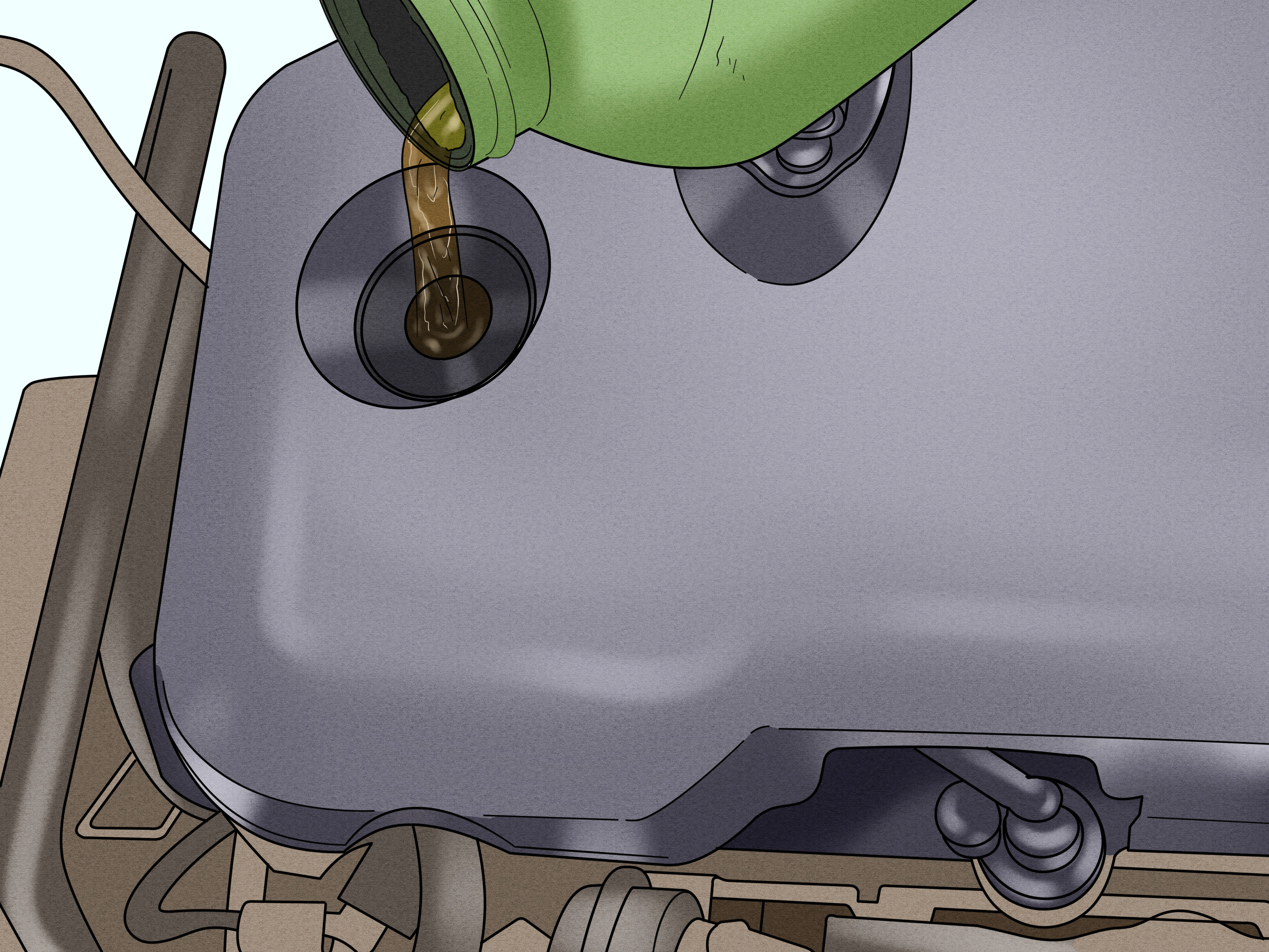
Install a new oil filter and refill the crankcase with the correct oil. Refill the cooling system with the specified coolant mixture and use the manufacturer’s bleeding procedure. Some vehicles require vacuum filling or dedicated bleed screws to remove trapped air.
Reconnect the battery, check for forgotten tools, and start the engine. Watch oil-pressure and temperature indicators closely. Inspect for fuel, oil, exhaust, and coolant leaks. Verify cabin-heater operation, cooling-fan cycling, and stable coolant temperature.
After the engine cools completely, recheck the coolant and oil levels. Inspect the oil for contamination and look for continuing bubbles, pressure buildup, smoke, misfires, or coolant loss. A final cooling-system pressure test or combustion-gas test can provide additional confirmation that the repair is sealing correctly.
Research support:
Experience-Based Lessons From Head Gasket Installation
The Best Repair Begins Before Disassembly
One of the most useful habits is creating a repair record before touching the engine. Write down compression readings, diagnostic codes, cooling-system pressure, evidence of coolant contamination, and the circumstances that caused the engine to overheat. These notes help separate the original problem from anything discovered during reassembly.
For example, suppose an engine overheated only while sitting in traffic. Replacing the head gasket without diagnosing a failed electric fan may produce a perfectly installed gasket that soon fails again. The new part cannot compensate for an old cooling-system problem. A head gasket is talented, but it is not a licensed miracle worker.
Organization Saves More Time Than Speed
During a long repair, dozens of bolts may appear almost identical. A simple cardboard template labeled “intake,” “timing cover,” and “accessory bracket” can prevent hours of confusion. Photographs should include wide views for routing and close-ups for connector locks, ground-wire locations, and bracket orientation.
A particularly useful technique is stopping after every major removal stage and reviewing what was disconnected. This catches hidden ground straps and wiring clips before the cylinder head is lifted. It also reduces the chance of discovering one lonely connector after the entire engine is back together.
Surface Preparation Requires Restraint
Many first-time installers assume that a bright, aggressively polished deck must seal better. In reality, removing material carelessly can make the surface less flat or produce a finish that does not match the gasket. A clean surface is necessary; a randomly remodeled surface is not.
Work slowly around the cylinders and fluid passages. Keep debris out of the engine, inspect the deck under strong lighting, and let a machine shop handle questionable damage. The cost of professional inspection is usually much lower than purchasing another gasket set, another bolt set, and another weekend supply of emotional resilience.
Torque Is a Procedure, Not Just a Number
Experienced technicians prepare the torque wrench, angle gauge, bolt map, lubricant instructions, and marker before tightening begins. Once the sequence starts, they avoid phone calls, snack breaks, and conversations about why the car is still occupying the garage.
A common mistake is remembering the final torque value while forgetting the staged sequence. Gradual tightening allows the cylinder head and gasket to load evenly. Another mistake is applying oil to bolts that were supposed to be dry, or using ordinary motor oil when an aftermarket fastener specifies a dedicated lubricant. Identical torque values can create different clamping loads when friction conditions change.
The First Start Should Be Calm and Deliberate
The first startup is not the moment to rev the engine triumphantly. Confirm fluid levels, scan the engine bay, and keep a hand near the ignition switch. Listen for timing-chain noise, valvetrain clatter, exhaust leaks, and unusual mechanical contact. Watch oil pressure and coolant temperature rather than admiring the fact that the engine started.
As the engine warms, the coolant level may change while trapped air moves through the system. Follow the prescribed bleeding method and never remove a pressurized cap from a hot engine. Once the cooling fan operates and the temperature stabilizes, shut the engine down if required by the procedure and allow it to cool fully before rechecking levels.
Finally, inspect the repair again after a short, gentle drive. Check around hose connections, manifolds, the valve cover, drain plugs, timing covers, and the cylinder-head joint. A small leak found now is an easy correction. A small leak ignored for several weeks may eventually introduce itself with steam, warning lights, and a tow-truck invoice.
Conclusion
Learning how to install a head gasket involves much more than replacing one sealing component. The engine must be diagnosed correctly, disassembled in a controlled order, measured for distortion, cleaned without damage, and reassembled with exact timing and clamping procedures.
The most important rules are simple: use vehicle-specific service information, correct the original cause of failure, verify the cylinder head and block surfaces, replace single-use fasteners, and follow every torque stage precisely. Patience may not appear on the parts receipt, but it is one of the most important tools in the repair.
Editorial note: This general procedure was developed from established engine-repair guidance published by gasket manufacturers, fastener manufacturers, repair-manual providers, automotive technical publications, and major parts retailers. Vehicle-specific factory procedures always take priority. seo-json”>