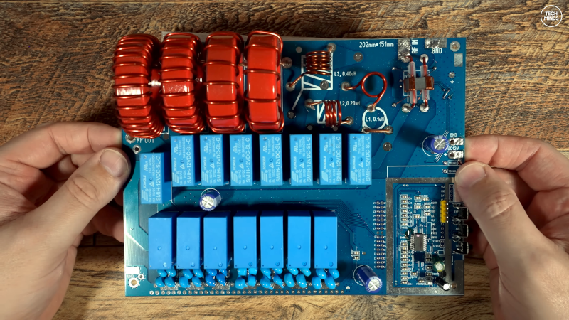
Every ham has met that piece of gear: the one that works perfectly right up until you need it to. In Hackaday’s
“What’s Wrong With This Antenna Tuner?” the mystery isn’t a puff of magic smoke or a relay welded shutit’s something
more annoying: an antenna tuner that sometimes tunes, sometimes refuses, and occasionally
seems to report SWR like it’s guessing based on vibes.
If you’ve ever watched an auto tuner rattle through relays like a caffeinated woodpeckeronly to land on a match that’s
“close enough” while your radio folds back power anywaythis story will feel familiar. The good news: the tuner often
isn’t “broken” in the dramatic sense. The bad news: the problem is usually a three-way misunderstanding between
the load, the measurement, and the laws of RF physics.
The core misunderstanding: tuners don’t “fix” antennasthey negotiate with them
Let’s get the biggest myth off the bench first: an antenna tuner doesn’t tune the antenna. It tunes the impedance
presented to the radio. Think of it like a translator at a noisy party. Your transmitter speaks “50 ohms,” your
antenna system replies in “who knows,” and the tuner tries to keep the conversation polite.
That’s why a tuner can give you a beautiful 1:1 SWR at the radio while the coax between the tuner and antenna is still
suffering from a mismatch, standing waves, and loss. If the mismatch is large and the feed line is lossy (coax on higher
bands is a usual suspect), you can lose a painful chunk of your power as heat before it ever reaches the antenna.
This is also why “put the tuner at the antenna feedpoint” is not just a clichéit’s a practical strategy. A remote tuner
close to the antenna can keep the long run of coax near 1:1 SWR, which is exactly where coax behaves best.
What’s inside many automatic tuners: a switched L-network and a truthy SWR sensor
Many modern auto tunerscommercial and DIYare basically two subsystems:
-
A matching network (commonly a switched L-network) made from inductors and capacitors, often switched
in binary steps with relays so the tuner can try many combinations quickly. -
An SWR measurement system (directional coupler + detector) that estimates forward and reflected power
so the controller can decide whether it’s getting warmer or colder.
A classic DIY example is the ATU-100 / N7DDC-style approach: relay-selected inductors and capacitors, plus a relay that
can swap whether the capacitor appears on the input or output side of the inductor (two L-network “orientations”).
That “flip” matters because the same values can match a load in one configuration and fail miserably in the other.
Commercial tuners use similar concepts. Even big-name units commonly limit tuning power during the tune cycle and rely on
their SWR sensor’s readings to drive an algorithmmeaning if the SWR sensor is inaccurate, the tuner is basically playing
hot-and-cold with a broken thermometer.
So what’s “wrong” in the Hackaday case? Usually one of these three things
1) The antenna system impedance is outside the tuner’s practical matching range
Many built-in radio tuners top out around a modest mismatch and will simply give up if the SWR is too high. External tuners
can be far more capable, but they still have limits determined by available inductance/capacitance, component voltage
ratings, and network topology.
A particularly common trap is the end-fed “random wire” setup. Certain lengths land you near half-wave multiples on
certain bands, which can produce very high feedpoint impedanceso high that a modest internal tuner (or a compact DIY
relay tuner) can’t find a workable transformation. The tuner isn’t being stubborn; it’s being outgunned.
The “fix” often isn’t another tuning attempt. It’s changing the system so the tuner has something reasonable to work with:
add a proper counterpoise, use a current balun/unun where appropriate, add a choke to control common-mode currents, or
adjust wire length to avoid worst-case impedances.
2) The SWR measurement is lyingespecially at low power
Auto tuners make decisions based on measured forward/reflected power. If the detector diodes are operating in a nonlinear
region (common at very low RF levels), if the coupler phasing is wrong, or if stray RF is sneaking into the control lines,
the tuner may “see” reflected power that isn’t actually reflected poweror miss reflected power that is.
One quick sanity check: SWR should be largely independent of power level. If your SWR reading changes dramatically when
you go from (say) 5 W to 50 W into the same load, that’s a big hint your measurement system is the problem, not the match.
For auto tuners, that can lead to bizarre behavior: it finds a “match” at tune power but looks worse at operating power, or
it endlessly re-tunes because it thinks the SWR keeps changing.
Another classic gotcha: putting an SWR meter on the antenna side of a tuner and expecting it to behave. Many meters
are designed to work properly in a 50-ohm environment; on the antenna side of a matching network, that assumption can be
wildly violated, producing “bizarre answers” that aren’t actually useful.
3) Stray RF and common-mode currents are interfering with the tuner’s brain
When the antenna system is unbalanced (many end-fed setups are), the feed line and anything connected to it can become
“part of the antenna.” That includes your tuner’s DC power cable, the control cable, and your radio’s chassis.
Congratulations: your station is now an interpretive art piece titled RF Everywhere.
Symptoms include: re-tuning during transmit, relays clicking when they shouldn’t, unstable SWR readings, and touchy
behavior that changes when you move cables around. The common cures are equally unglamorous: add ferrite chokes to DC and
control leads, improve station grounding strategy, add a proper choke at the feedpoint, and confirm your counterpoise/radials
are doing real work rather than symbolic work.
Antenna tuner troubleshooting: a practical, low-drama checklist
If you want to troubleshoot like a grown-up (and not like a raccoon in a parts bin), start by separating the system into
testable chunks.
Step 1: Prove the tuner and SWR sensor with a known-good load
-
Connect a 50-ohm dummy load at the tuner output.
Your tuner should either bypass cleanly or find a 1:1 match quickly. -
If it can’t, suspect the SWR coupler/detector wiring, relay wiring, or a bad component value (wrong capacitor bank,
incorrect inductor turns, mis-phased transformers).
Step 2: Test with a few “known wrong” loads
A dummy load is a “pass” test. You also want a controlled “fail” test:
- Try 100 ohms (expect a mismatch without tuning, then a match after tuning).
- Try 25 ohms (ditto; some networks struggle more at very low impedance).
-
If you’re comfortable and know what you’re doing, an open/short test can expose coupler directivity problemsjust keep
power low and don’t leave it transmitting.
Step 3: Check SWR stability versus power
- Measure SWR at 5 W and 25 W into the same resistive load.
-
If the number changes a lot, suspect diode detector nonlinearity, saturation, or coupling issues.
An auto tuner depending on that signal will “hunt” and misjudge.
Step 4: Make sure the tuner has enough L and C for the job
An L-network is efficient and popular, but it’s not magic. If your tuner tops out at a certain inductance or capacitance,
there will be real-world loads it cannot match. This becomes obvious on bands where the antenna is far from resonance or
where the feedpoint impedance swings to extremes.
Practical fixes include increasing maximum inductance (more turns or more inductors in the bank), increasing capacitance
(additional capacitor steps), or using a different topology (some manual T-networks cover a wider impedance range).
Step 5: Reduce stress and lossespecially if you’re using a T-network
T-networks are famous for matching “anything,” but that flexibility comes with tradeoffs: higher circulating currents and
higher voltages across capacitors, which can increase loss and encourage arcing if you push power into ugly loads.
If you’re routinely matching very low impedances or operating with high SWR on coax, expect more heat and more drama.
That drama may look like intermittent tuning failuresespecially as components warm, drift, or arc under high voltage.
Step 6: If it’s an end-fed/random wire, treat length and counterpoise as tuning controls
“Random wire” is a nickname, not a guarantee. Certain lengths are notorious for presenting extremely high impedance on
some bands (often around half-wave multiples), which can defeat typical tuners.
-
Use a counterpoise or radials sized for at least the lowest band you care about.
Without it, the system invents one (often your coax shield and station wiring). -
If your tuner consistently fails on one band, try a meaningful wire-length change (not 2 inchesthink feet).
You’re trying to move away from an impedance “cliff,” not repaint it. - Add a choke at the feedpoint to keep RF off the outside of coax and out of your tuner’s DC/control cables.
Step 7: Don’t ask your tuner to compensate for a bad feed line plan
If you’re running high SWR on coax at higher HF frequencies, line losses rise. A tuner in the shack can make the radio happy,
but it can’t undo the physics of power bouncing back and forth along a lossy transmission line.
If the antenna is far away and mismatched, consider ladder line (low loss even at high SWR) or consider a remote tuner
near the antenna feedpoint. You’re not “cheating.” You’re relocating the impedance transformation to where it’s most
effective.
How you know you’ve actually fixed it
A healthy system has a few boring propertiesboring is good in RF:
- The tuner finds a match in a reasonable time and doesn’t immediately re-tune during transmit.
- SWR readings are consistent over modest power changes.
- Your radio stops folding back power (or at least does so less often).
- Touching cables doesn’t “change the antenna.”
If you achieve all that, congratulations: you’re no longer debugging an antenna tuner. You’re doing what hams have always
donebuilding an RF system that behaves.
Field Experiences and Lessons Hams Commonly Report (Extra )
The funniest thing about antenna tuners is that they’re often blamed for crimes committed by everything else. In countless
shack stories, the tuner becomes the scapegoat because it’s the box with lights, buttons, and that dramatic relay clatter.
Meanwhile, the real culprit is a “temporary” antenna install that has been “temporary” for three years.
A very common experience: someone builds or buys an auto tuner, connects it to an end-fed wire, and it tunes beautifully on
two or three bands. Then one band refuses to cooperate, the tuner cycles endlessly, and the operator starts suspecting bad
relays, bad firmware, or a cursed toroid. What changes band-to-band isn’t the tuner’s personalityit’s the impedance at the
antenna feedpoint. On the “good” bands, the tuner is doing normal impedance transformation. On the “bad” band, the antenna
system has wandered into a region where impedance is extreme, reactive, or both. The tuner may hit its L/C limits, or it may
find a theoretical match that demands capacitor voltage or inductor current the hardware can’t tolerate at real operating
power.
Another repeat offender is RF in the shack. Operators report tuners that “won’t hold a match” or that re-tune
whenever they touch the microphone, key the amp, or even swivel the chair. In many cases, the tuner is being tricked by RF
getting into its control lines or DC cable. Add ferrite chokes, shorten and reroute cables, and suddenly the “defective” tuner
becomes “reliable.” The best part is the emotional arc: the tuner did not improve. The station stopped acting like a
science-fair Tesla coil.
People also learnsometimes the hard waythat measurement tools have assumptions. Put a meter where it expects
50 ohms, and it behaves. Put it on the antenna side of a tuner where impedance is transformed and sometimes highly reactive,
and it can display numbers that look precise but aren’t meaningful. Many operators have chased phantom SWR spikes for hours
because the meter location was telling them a story it was never designed to tell.
Finally, there’s the “small change, big outcome” lesson: moving a tuner closer to the antenna, adding a real counterpoise,
or changing wire length by several feet can transform a system from “won’t tune” to “tunes instantly.” That’s not mystical.
It’s simply shifting the impedance landscape into a region where your tuner’s L-network and component ratings can do their job
efficiently. When that happens, the relays stop sounding like a blender full of marbles, your radio stops sulking, and you get
back to the part of the hobby that’s supposed to be fun: making contacts instead of making new swear words.
Conclusion: the tuner is asking for a better deal, not filing for divorce
Hackaday’s antenna tuner mystery is a perfect reminder that “won’t tune” is usually not a single failureit’s a mismatch
between expectations and the RF reality of the system. The tuner can only transform what it sees, using the measurements it
trusts, inside the limits of its components. If the load is extreme, the measurement is inaccurate, or RF is leaking into places
it shouldn’t, the tuner will behave like it’s broken even when it’s electrically fine.
Fix the measurement. Control common-mode. Give the tuner a load inside its range. And if all else fails, remember the oldest
ham troubleshooting technique: change one thing at a time and keep snacks nearby.